
System Introduction
Rotation Sensor
Bail Angle Sensor
Block Extend Sensor
RigSense
Anti-Collision
System
Anti-Collision
System
Rev 1.0
System Introduction
Overview
Anti-Collision System Components
Key Benefits
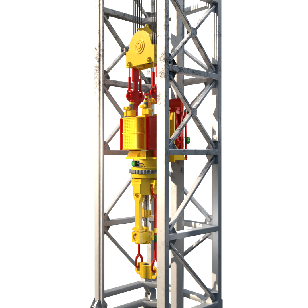
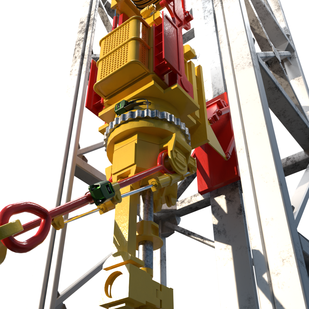
The RigSense Anti-Collision System prevents contact between the top drive, racking board, derrick structure and all pipe handling equipment. Constant communication between the RigSense wireless components and display panel ensure that all equipment moves safely within precisely controlled working zones.
RigSense is dedicated to making rigs everywhere safer and more efficient by helping avoid equipment collisions and limit NPT.
RigSense is dedicated to making rigs everywhere safer and more efficient by helping avoid equipment collisions and limit NPT.
System Components
Rotation Sensor:
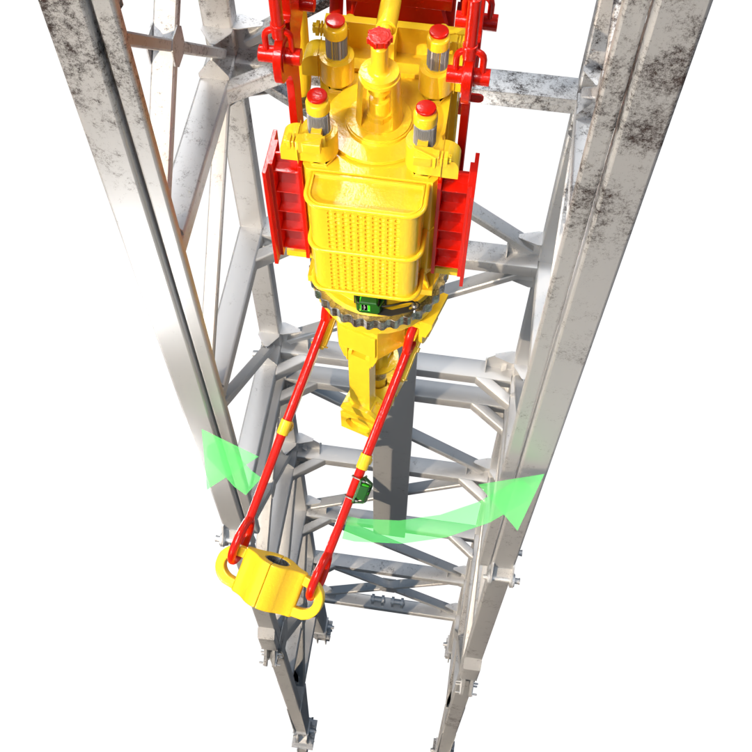
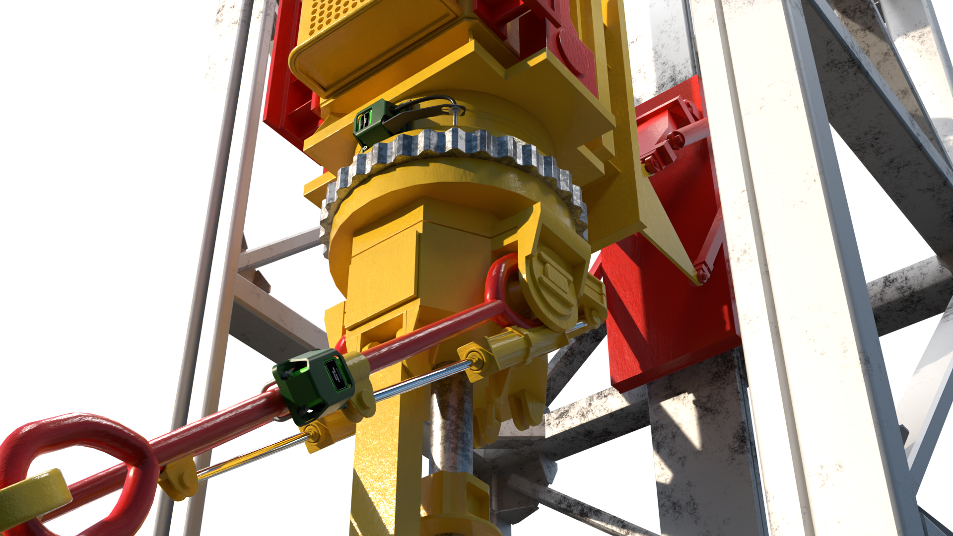
The rotation sensor measures rotation of the elevator in both directions from a ‘zero’ point.
Bail Angle Sensor:
measures the angle of the bails.
Block Extend Sensor:
measures the distance between the top drive and the back of the derrick.
The rotation sensor measures rotation of the elevator in both directions from a ‘zero’ point.
Bail Angle Sensor:
measures the angle of the bails.
Block Extend Sensor:
measures the distance between the top drive and the back of the derrick.
Rotation Sensor
Rotation Sensor - Overview

This is some text inside of a div block. This is some text inside of a div block. This is some text inside of a div block. This is some text inside of a div block. This is some text inside of a div block. This is some text inside of a div block. This is some text inside of a div block. This is some text inside of a div block.
Rotation Sensor Info Screen
This is some text inside of a div block. This is some text inside of a div block. This is some text inside of a div block. This is some text inside of a div block. This is some text inside of a div block.
Rotation Sensor - Installation
Component List
1: Sensor Guard - painted stainless steel, protects sensor body from collisions with other equipment
2: Battery Lid Screws - 1/4-20 UNC-2A x 1/2" machine screws
3: Battery Lid - secures the battery compartment
4: Lithium Battery - 3.6V Lithium Ion
5: Sensor Body - Ultramid 8333G Hi-Polyamide 6
6: Sensor Mounting Bracket - painted stainless steel, secures the sensor and Hall effect cable
7: Sensor Mounting Bracket Hardware - 1/4-20 UNC-2A x 1" bolts with washers
8: Mounting Plate Hardware - 1/4-20 UNC-2A x 2" bolts
9: Mounting Plates - painted stainless steel welded to rotator hub, secures sensor bracket to top drive
Explode/Assemble Rotation Sensor
Rotation Sensor - Calibration
This is some text inside of a div block. This is some text inside of a div block. This is some text inside of a div block. This is some text inside of a div block. This is some text inside of a div block. This is some text inside of a div block. This is some text inside of a div block. This is some text inside of a div block.
This is some text inside of a div block. This is some text inside of a div block. This is some text inside of a div block. This is some text inside of a div block. This is some text inside of a div block. This is some text inside of a div block. This is some text inside of a div block. This is some text inside of a div block.
div block. This is some text inside of a div block. This is some text inside of a div block. This is some text inside of a div block. This is some text inside of a div block.
This is some text inside of a div block. This is some text inside of a div block. This is some text inside of a div block. This is some text inside of a div block. This is some text inside of a div block. This is some text inside of a div block. This is some text inside of a div block. This is some text inside of a div block.
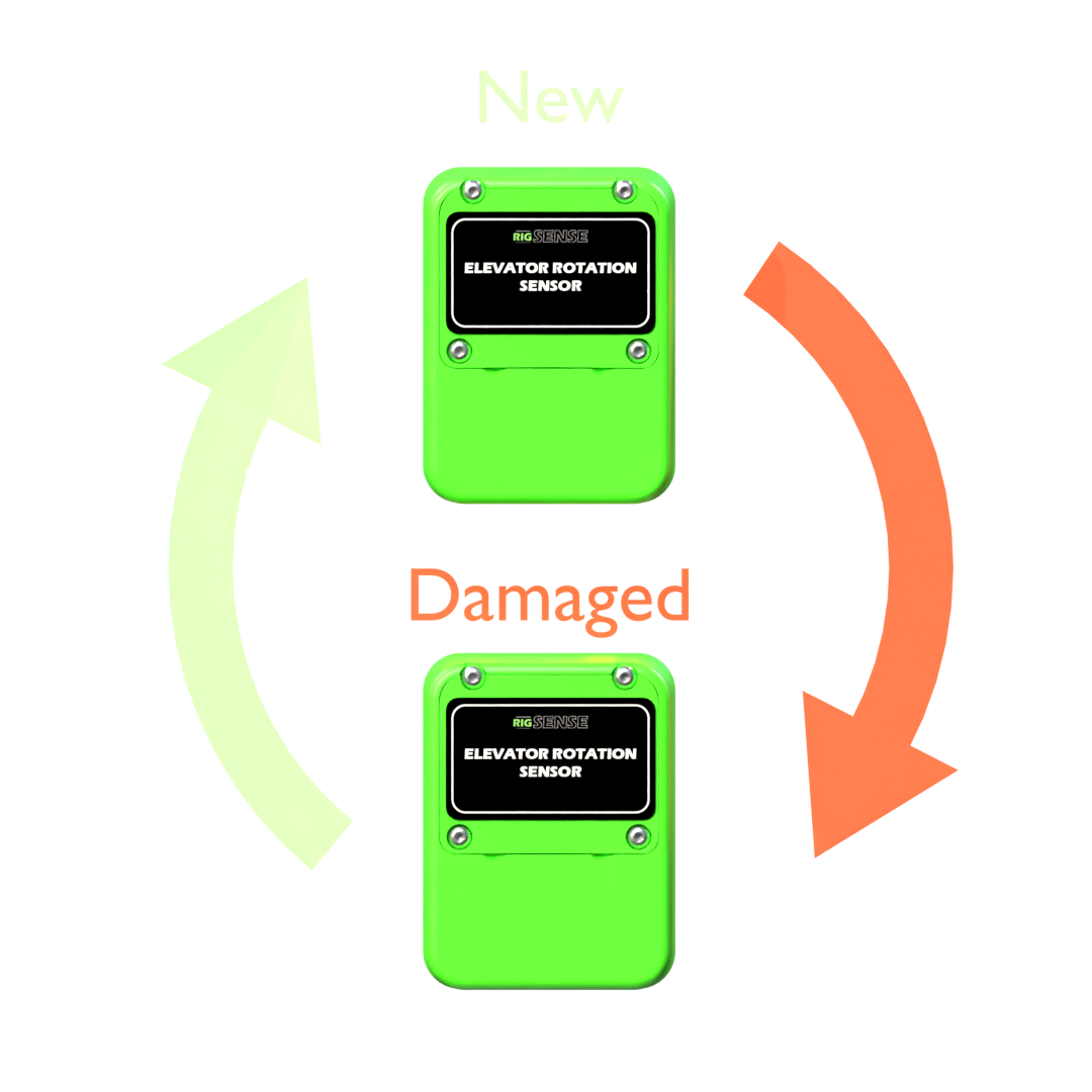
Rotation Sensor Calibration
Service - Swapping Components
This is some text inside of a div block. This is some text inside of a div block. This is some text inside of a div block. This is some text inside of a div block. This is some text inside of a div block. This is some text inside of a div block. This is some text inside of a div block. This is some text inside of a div block.
1: Detach Hall effect sensor from mounting bracket arm
2: Unscrew sensor guard hardware from mounting plates
3: Remove sensor guard
4: Unscrew sensor mounting bracket hardware
5: Remove rotation sensor body with cable and Hall effect sensor
6: Insert new rotation sensor body into mounting bracket
7: Secure new rotation sensor to mounting bracket with mounting bracket hardware
8: Secure new Hall effect sensor around mounting bracket arm
9: Secure sensor guard over new rotation sensor with sensor guard hardware
10: Secure sensor guard to mounting plates
Swapping Rotation Sensor
back
image
rotation
sensor
sensor
bail angle
sensor
sensor
block extend
sensor
sensor
Rotation Sensor
Description
Uses RFID technology to detect the operational areas in a full 360° rotation. This positional information is then displayed on the user panel. The rotation sensor is typically installed in approximately one hour and can be fit to any type of top drive with rotation capabilities. The accuracy of the sensor is well within 0.1° and provides real-time feedback to the panel.
Operating Temperature
-35° C - 65°C (-31°F-149°F)
Power Source
Powered by 12 or 24V DC, supplied by crane
Materials
Body material – Ultramid 8333G Hi-Polyamide 6 Seals – ROHS compliant silicon rubber, 60 durometer shore-A, compound # SIM40160
Hazardous locations
Class 1, Div 2, C&D T4 Ex nA IIB T4
Bail Angle Sensor
Description
A wireless component which mounts onto the bails and transmits positional information to the central display panel.The bail angle sensor is typically installed in approximately 30 mins and can be fit to any type of top drive bail arms. The accuracy of the sensor is well within 0.1° and provides real-time feedback to the panel.
Operating Temperature
-35° C - 65°C (-31°F-149°F)
Power Source
Powered by 12 or 24V DC, supplied by crane
Materials
Body material – Ultramid 8333G Hi-Polyamide 6 Seals – ROHS compliant silicon rubber, 60 durometer shore-A, compound # SIM40160
Hazardous locations
Class 1, Div 2, C&D T4 Ex nA IIB T4
Block Extend Sensor
Description
A wireless transducer that monitors the angle of extension between the back of the top drive and the inner face of the derrick. This positional information is then displayed on the user panel. The block extension sensor is typically installed in approximately 20 mins and can be fit to any type of top drive with extension capability. The accuracy of the sensor is well within 0.1° with real-time feedback to the panel.
Operating Temperature
-35° C - 65°C (-31°F-149°F)
Power Source
Powered by 12 or 24V DC, supplied by crane
Materials
Body material – Ultramid 8333G Hi-Polyamide 6 Seals – ROHS compliant silicon rubber, 60 durometer shore-A, compound # SIM40160
Hazardous locations
Class 1, Div 2, C&D T4 Ex nA IIB T4
rotation sensor
brief component description here
bail angle sensor
brief component description here
block extend sensor
brief component description here